Click to view a short movie of the rotating lighthouse, installed beside the front door.
I think of this project as a kind of lighthouse, even though it has nothing in common with a maritime navigation aid except that it's lit up at night and it rotates.
A lighthouse has an intense, tightly focused beam. This project uses a 13 watt fluorescent tube whose light will be as diffused as possible.
A lighthouse beam rotates, shining through fixed clear windows. This project has a stationary lamp and rotating colored glass.
A lighthouse is a tall building so the light can be seen miles from shore. This project will sit about a foot off the ground and will be visible for maybe a hundred meters.
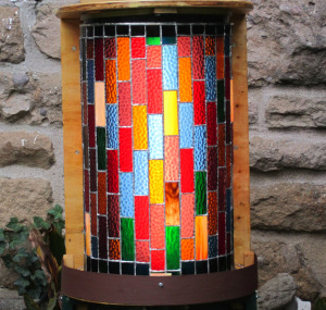
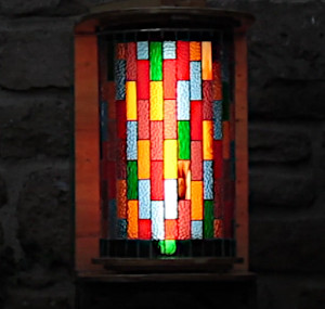
Before getting into the construction story, let's begin with the "beauty contest" views, namely short movies of the (mostly) finished lighthouse by day and by night.
Click to view a short movie of the rotating lighthouse, installed beside the front door.
Building the lighthouse was not a straight-line progression from idea to finished goods. In the photos below, you may notice details that appear or disappear. That's because there were a few missteps and detours along the way.
Click an image to view its enlargement
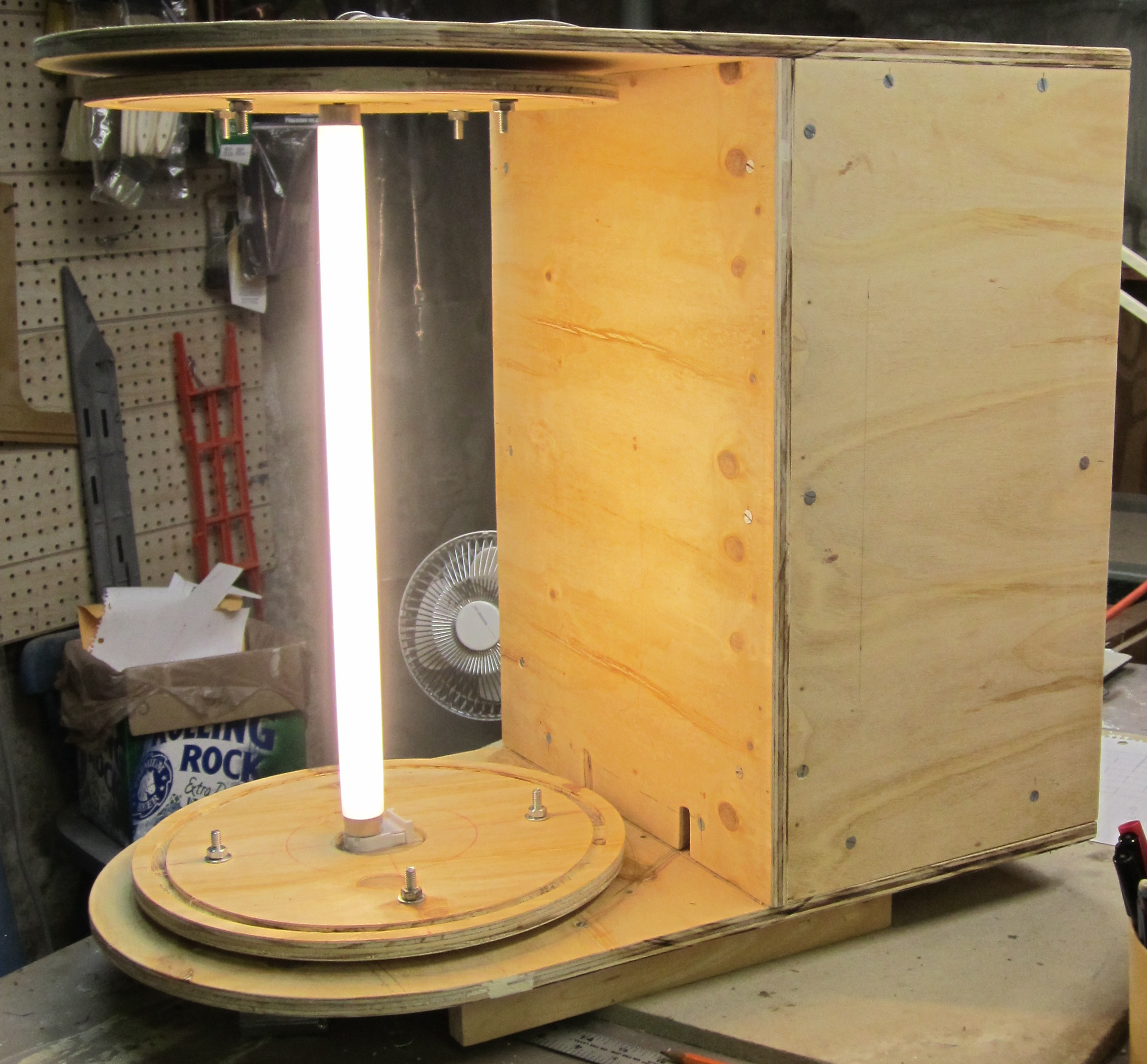
I began by making the plywood housing. The concept was that a rotating glass cylinder would be supported top and bottom by turntables that ride on “lazy susan” bearings. (Quite good bearings are about $6-7 from your local building center). It would be illuminated by a fluorescent light at the center, and all other electrical stuff would be housed inside the box.

Latest attempt at a drive system.
Turntable. In the initial plan, the turntable would be driven by a small DC motor that I salvaged from a dead ink-jet printer. A belt would transmit drive power to the lazy susan. Direct drive — gears or idler wheels — was ruled out because I knew the turntable might be imperfectly round and might be mounted a tad off-center.
Getting power from the motor to the turntable was harder than I expected, and involved a number of false starts and wrong turns. I'm currently at the "Plan E" stage, using an AC motor salvaged from an old toy.
This version works, sort of. Meanwhile, let's talk about the rest of the construction.
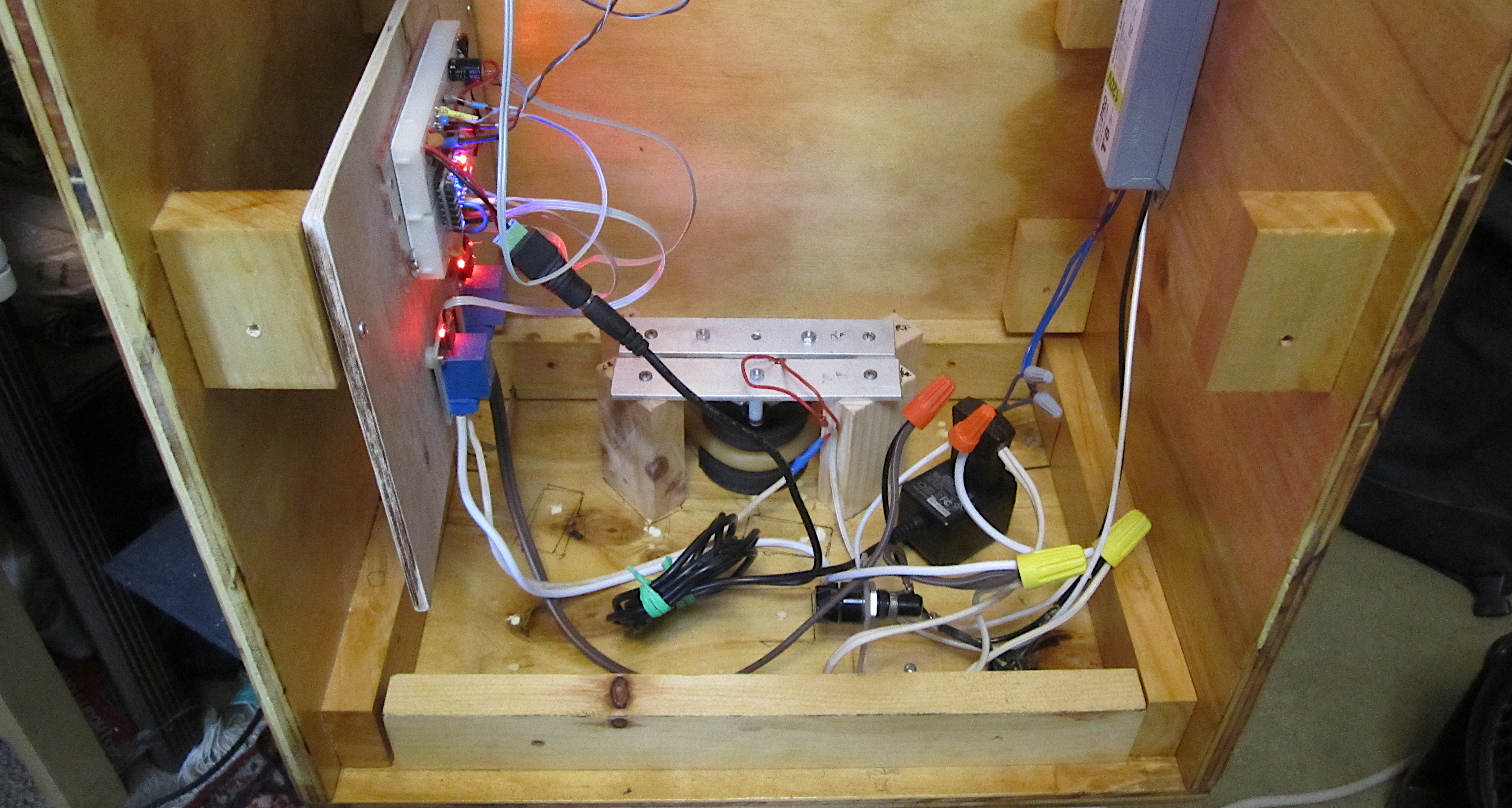
Inside the box. Although the main function of the box is to provide rigid support for the fluorescent lamp and rotating glass, it also provides shelter for the electronic parts. In the photo above, you can see:
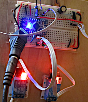
Closeup of the controller. A no-longer-needed DC motor chip left empty space on the breadboard. The control program uses only 20% of available RAM in the Arduino ProMini and fewer than half of the I/O pins. Plenty of room for future options.
Mounted outside the box are:
The stained glass. From the foregoing, you might think this was a woodworking project. On the stained glass side, things were much simpler. Cutting the glass sheets into strips and the strips into panels, a repetitious task, was eased by using jigs. Edging each panel (all 240 of them) with copper foil took many hours, but there's no story to be told; I just slogged through it. Where things got interesting was assembling all the panels into a cylinder.
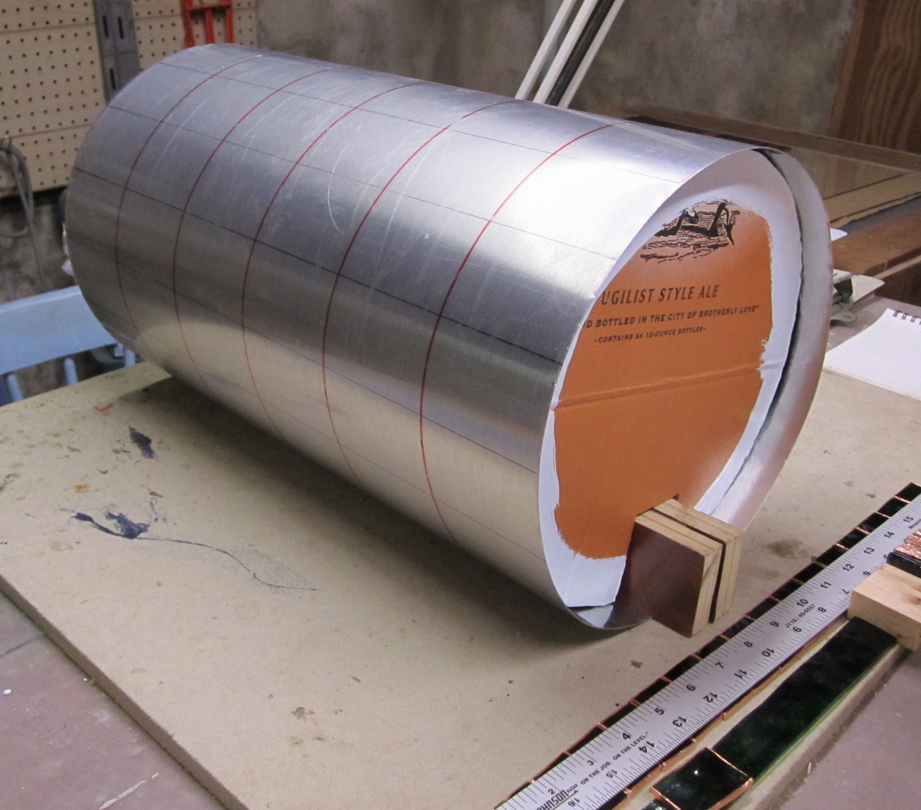
The natural springiness of sheet metal kept the curvature smooth, but it tended to sag into an oval shape. To prevent this, circles cut from cardboard were stuffed inside.
Forming the cyclinder. As with the jack-o-lantern project, the glass pieces were assembled on a scaffold. The math said that I needed a 32-inch circumference, so the form was made of a 36-inch piece of sheet aluminum, with two inches at each end bent inward to hold the cylinder closed. To keep the cylinder round instead of oval, the inside was braced with several cardboard circles. On this form I laid up the glass pieces, holding them in place with painter's tape, and then soldered them all together.
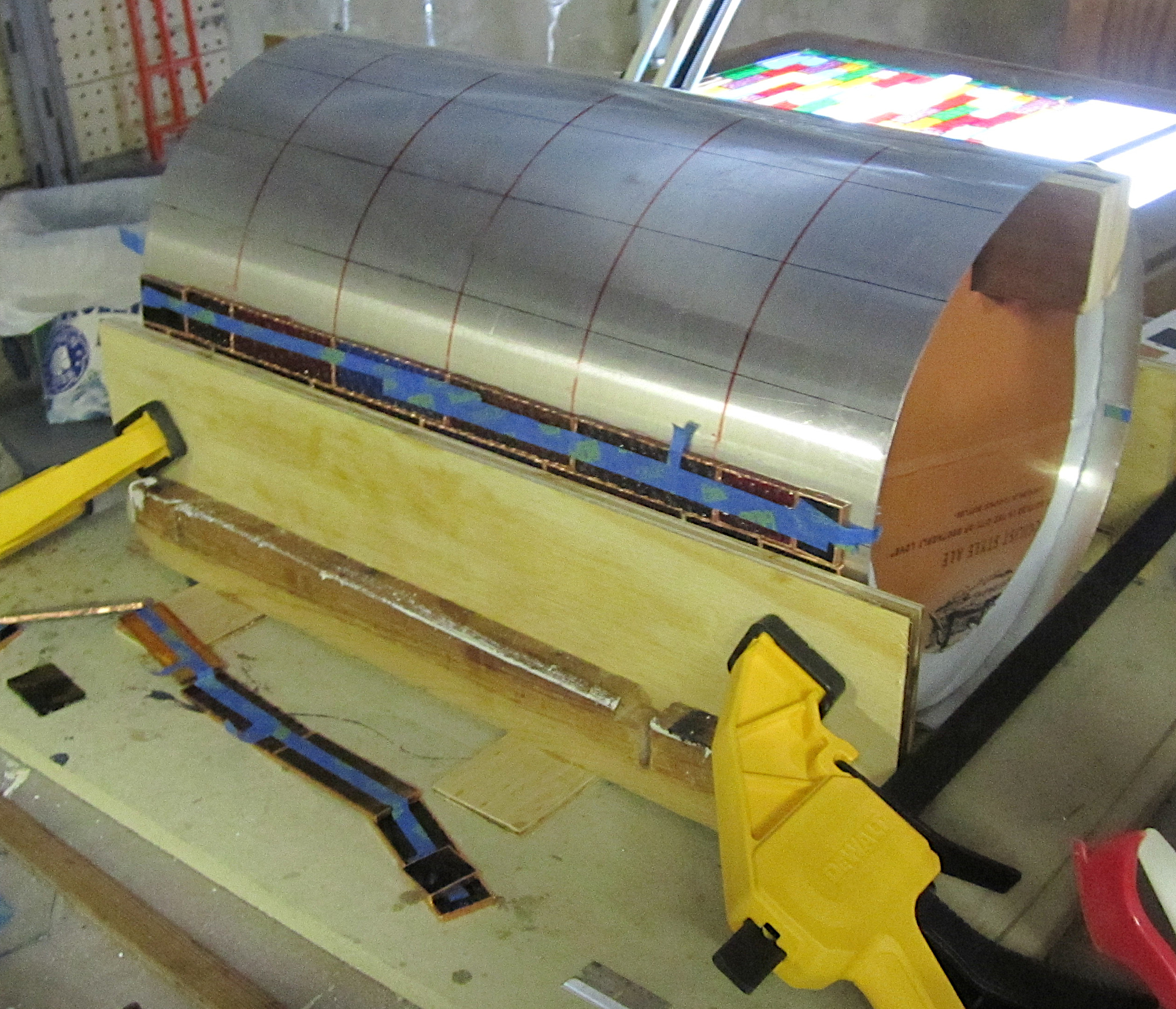
The glass pieces were laid against the scaffold and held in place with tape. Unfortunately, soldering flux dissolves the tape's glue. Fortunately, I only needed the tape for the first couple of rows, which are nearly vertical. After that, new rows became more horizontal and gravity started to help more than it hurt.
When the outside seams were all soldered, it was easy to disassemble the scaffolding and pull it out from the center. As I'd hoped, the solder holding the glass pieces together did not stick to the aluminum. (Zinc-plated sheet metal is much cheaper, but solder sticks to zinc.) In fact, the gooey solder flux made the aluminum slippery so it slid right out.
That's when I discovered that, soldered only on the outside, the glass cylinder was not rigid enough to hold its shape. It sagged into an oval. So I quickly slid the scaffolding back in and restored circularity. Sliding the scaffold partway out, I soldered half the inside seams. Then I turned the work around, slid the scaffold out the other end, and soldered the other half of the seams. After that, the cylinder stayed circular when the scaffold was removed. But for extra strength, I added a thin strip of brass all the way around the top and bottom edges.
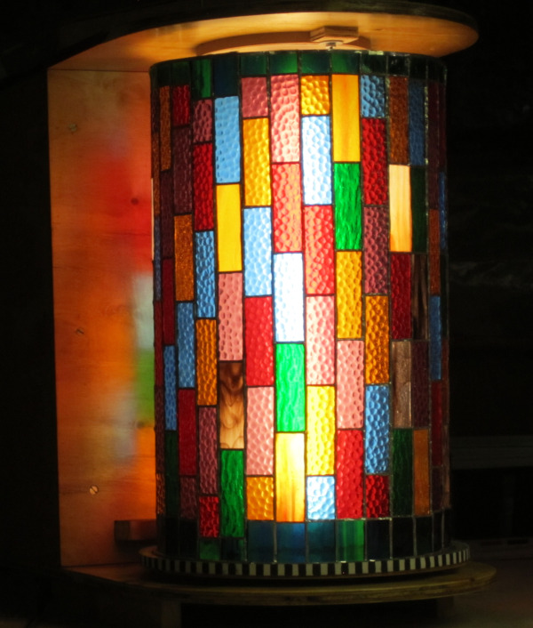
The almost-finished project, assembled for a dress-rehearsal round of testing.
First tests. Initial testing revealed a few design errors and construction mistakes.
The top and bottom turntables weren't perfectly aligned and, with the glass cylinder in place, they would jam at various points in the rotation. The simplest cure was to remove the top turntable. That left a gap of about 1½ inches between the top of the cylinder and the roof of the enclosure. Not only was this gap ugly, but bugs drawn to the light could fly right in.
The cure was to suspend a curtain of black polyethylene from the roof into the cylinder. Amost nothing sticks to polyethylene, so I clamped the plastic between the halves of an embroidery hoop.
The motor made a loud singing noise whenever it was running below full power. The pitch was close to a middle-B (490 Hz), which indicated that it was caused by the controller's pulse-width modulation of the motor voltage. (It was probably some sort of resonance with the motor mounts and case.) Fortunately, it was easy to change the controller's frequency. Not knowing whether to go much lower or much higher, I opted for the lowest available frequency, 31 Hz. That worked well enough that I didn't try other options.
I was concerned that the turntable rotation could be stalled, due to weather or wild animals or malign spirits. Even if I couldn't prevent this, I could detect it. Then I could try to shake off the jam and resume operation; or failing that, shut off the motor to prevent burnout.
With a black permanent marker, I inked stripes on the white rubber band at quarter-inch intervals. Then I aimed a reflection photodetector at the alternating white and black stripes, feeding the signal into one of the controller's analog-input pins. The controller could then measure how much time elapsed from one stripe to the next. If too much time went by, the controller could invoke a "panic" routine of some sort.
The stall detector worked (or did it? see below), but created a new problem: The black-and-white striped rubber band was too visible; it distracted from the colored glass. So I installed a strip of sheet metal as a visual barrier.
These changes entailed several new holes in the plywood case and made other holes redundant. So I took everything apart again, sealed the surplus holes with wood putty, and varnished the new holes and wooden pieces that got added along the way.
Second tests. The lighthouse failed again in second-round testing. I installed it outdoors to run non-stop for a few days. It worked fine for two nights. But on the third night, the weather changed to a misty rain, interspersed with heavy downpours. Both rubber bands got wet and the lighthouse stopped rotating. The stall detector and panic routine did their thing, but wet rubber has no friction against wet brass, and the machine's attempts at restarting — one try per minute — were in vain.
This was Plan B on the wrong turns page. Plans C and D had their own flaws.

The lighthouse in its intended outdoor location, next to my front door.
Status as of November 18, 2018. The lighthouse, using the "Plan E" drive has been outdoors for more than a week. During one wet rainy day, one snowstorm, and wide daytime temperature swings, the machine has kept on working, mostly. Annoyingly, the rotation is a bit jerky, which I suspect is caused by the stretchiness of the latex.
There may yet be a Plan F, but so far all my bright ideas have needed either precision manufacturing (beyond my skills) or store-boughten parts (beyond my willingness to pay). So for now, enough is enough.