First attempt at a drive system. The duct-tape belt was strong, but the system still failed.
Getting drive power from the electric motor to the turntable was ... educational, let us say. I learned that mechanics can be difficult and that precision matters a lot.
First attempt at a drive system. The duct-tape belt was strong, but the system still failed.
Plan A. Initially, I tried a single belt made from two strips of duct tape stuck together, inspired by a YouTube video. An idler wheel would take up any slack in the belt.
As I soon found out, this did not work — but not because the belt failed. (In fact, scientific tests have shown that duct tape is quite good for just about everything except taping ducts.) Rather, there were two other problems.
One was keeping the belt at the correct tension to pull the weight of the glass-laden turntable. Too little tension and the belt would slip, too much tension and the motor would stall. But, as I had expected, the turntable was rotating just a bit off-center, due to small errors in drilling the bolt holes. This meant there was no "Goldilocks zone" where the belt tension was just right. Pushing the idler wheel against the belt with some sort of spring might work better, but my mechanical skill wasn't up to that.
The other problem was that I wanted the glass to rotate at a very slow pace. With the motor that I had on hand, at full voltage the motor spun the turntable too fast. Reducing the voltage slowed the motor, but gave too little power to reliably overcome friction in the turntable.
So, on to Plan B.

Second attempt at a drive system. This worked fine in dry weather, but when the rubber band got wet, it lost traction.
Plan B was to use two drive belts: one from the motor to the large wheel of an intermediate pulley, and the other from the pulley's small wheel to the turntable. The pulley would act to gear down the final speed, allowing the motor to run faster (thus putting out more power) while moving the turntable quite sedately. And using rubber bands as drive belts solved the whole tension problem — or anyway, transformed it into a search for rubber bands of the right size.
I made the pulley by gluing a 1-inch plastic wheel (actually a gear stolen from a FischerTechnik construction set — it's like a Meccano or Erector Set, but aimed at younger children) onto a piece of 5/32-inch brass tubing. The axle was a 1/8-inch brass rod, which happens to fit nicely inside the 5/32 brass tube. With these dimensions, the pulley yields a 6:1 step-down in speed, with a corresponding step-up of torque.
My wife solved the rubber-band search problem at the supermarket, where she found a band designed for holding garbage bags in place. It was labeled as a "15 inch band", but the actual circumference of the loop was 30 inches — just right for the 34-inch outer circumference of my turntable. The small amount of stretch provided a good grip on the intermediate pulley, but no fear that it would break under the strain.
The belt from motor to intermediate pulley was a recycled Post Office rubber band.
At first, this looked like a winner. Alas, when it came time to field-test this technique, Plan B failed miserably. One night it rained; the large rubber band got wet and slid freely over the brass tubing. Nothing for it but to think up something for Plan C.
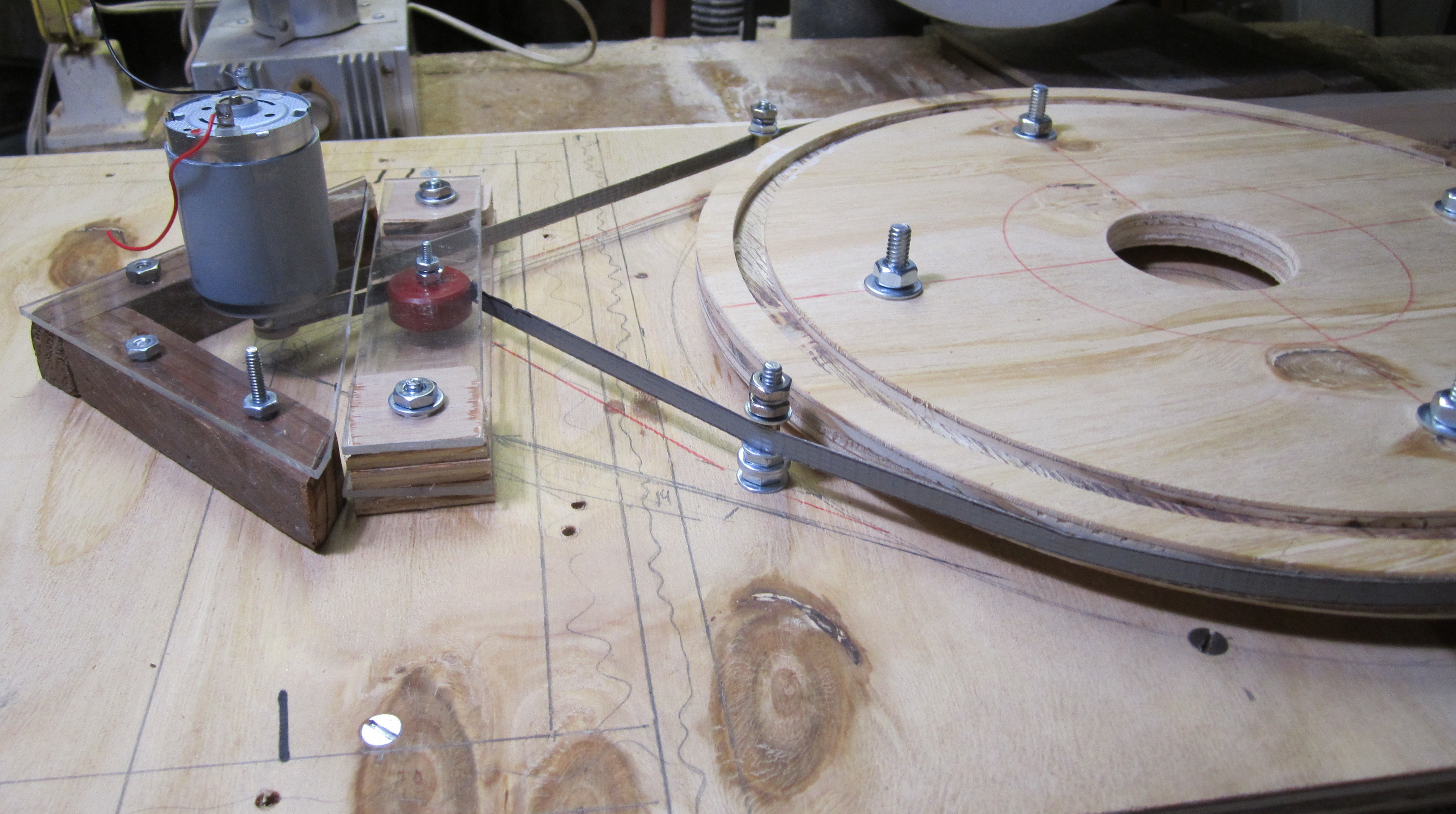
Third attempt at a drive system. This one didn't provide enough speed reduction.
Plan C. This was another two-belt scheme, with (hopefully) better materials. A loop of latex tubing replaced the large rubber band, and an o-ring replaced the small rubber band. The local building-supply store sold me a ten-foot piece of latex tubing, enough for several drive belts. To form a length into a loop, I coated a thin strip of latex with glue and shoved it into the open ends to hold them together. I used a glue called "E6000," which sticks nicely to rubber and stays fairly flexible after it cures.
Not having access to a lathe or a 3D printer, I used two sizes of hole saws to obtain round shapes for the two small pulley rollers. To refine the shapes, I tightened a bolt through each center hole and chucked the bolt into an electric drill strapped to a table — a poor man's lathe.
The large pulley roller (in the photograph, it's out of sight under the turntable) had a nine-inch diameter — bigger than any hole saw. Instead, I used a router and trammel-point guide to cut two disks out of quarter-inch plywood, using a U-shaped bit. By gluing the disks together face-to-face, I got a half-inch disk with a concave groove around the edge.
This setup almost worked. Testing revealed that latex tubing and o-rings have enough strength and elasticity to drive the turntable. However, a single intermediate pulley did not sufficiently reduce the drive speed. In retrospect, doing a bit of math beforehand could have predicted this.

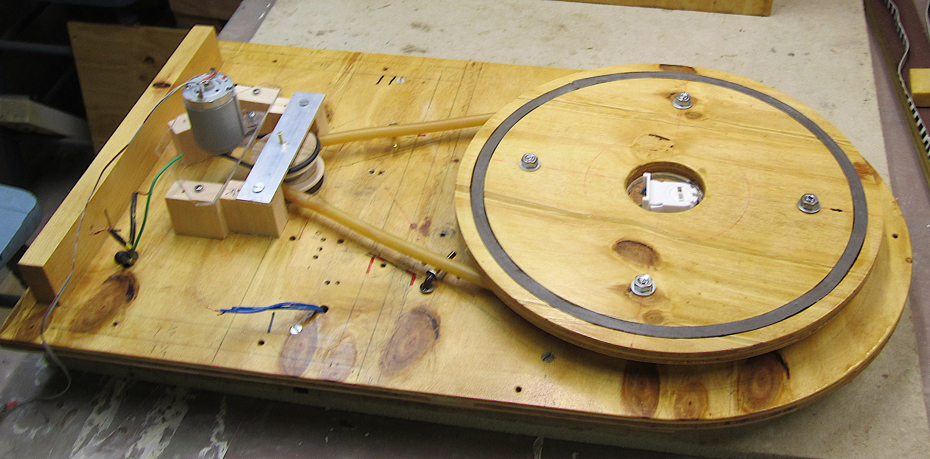
Fourth attempt at a drive system. Using two speed-reduction pulleys got the turntable rotating slowly enough. But the friction was too great.
Plan D. The fourth attempt built on the near-success of the third try: I added one more speed-reducing pulley to the drive train. This got the turntable speed down, but it also created more friction. Under full operating load with all glass and shrouds in place, this proved to be fatal; at any speed setting, the turntable would eventually stall. The stall detector would successfully restart the rotation, but within a few minutes it would stall again.
Once again, back to the old drawing board.

Fifth attempt at a drive system, using a small AC motor with internal gear train. No speed control, but maybe we can live with that.
Plan E. From the junkbox, I dug out a small AC motor from a broken toy. Its label said “14 RPM” which, using the toy wheel that the motor once drove as a pulley, would reduce to somewhere between one and two RPM on the turntable. A quick test showed that the motor had plenty of torque.
The downside was the controller chip wouldn't be able to vary the speed of the motor, which is determined by the frequency of the AC. However, the motor could easily be turned on and off with a small DC relay, so turntable stalling could still be addressed.
The motor's plastic wheel was hooked to the latex-tubing loop from Plan C. As before, this worked nicely in the shop but would slip and slide when it got wet.
To overcome this, I first tried violin-bow rosin. I dissolved a small chunk of rosin in alcohol, painted it on the wheel and the latex, and let it dry. Sure enough, this gave more traction — for a while. Running steadily over the course of a day, however, the rosin wore off. And, I soon discovered, even a well-rosined wheel would slip when it got wet.
Next, I tried covering the pulley with rubber bands to see whether that might have some traction when it was wet. And lo! This seemed to work even in the rain.
But not well enough; the turntable's rotation was a bit jerky. Since the motor wheel's rotation seemed perfectly smooth, the problem was probably due to elasticity of the latex tubing.
Plan F. As yet, there is no Plan F, just lots of hazy conjectures about what might work better.
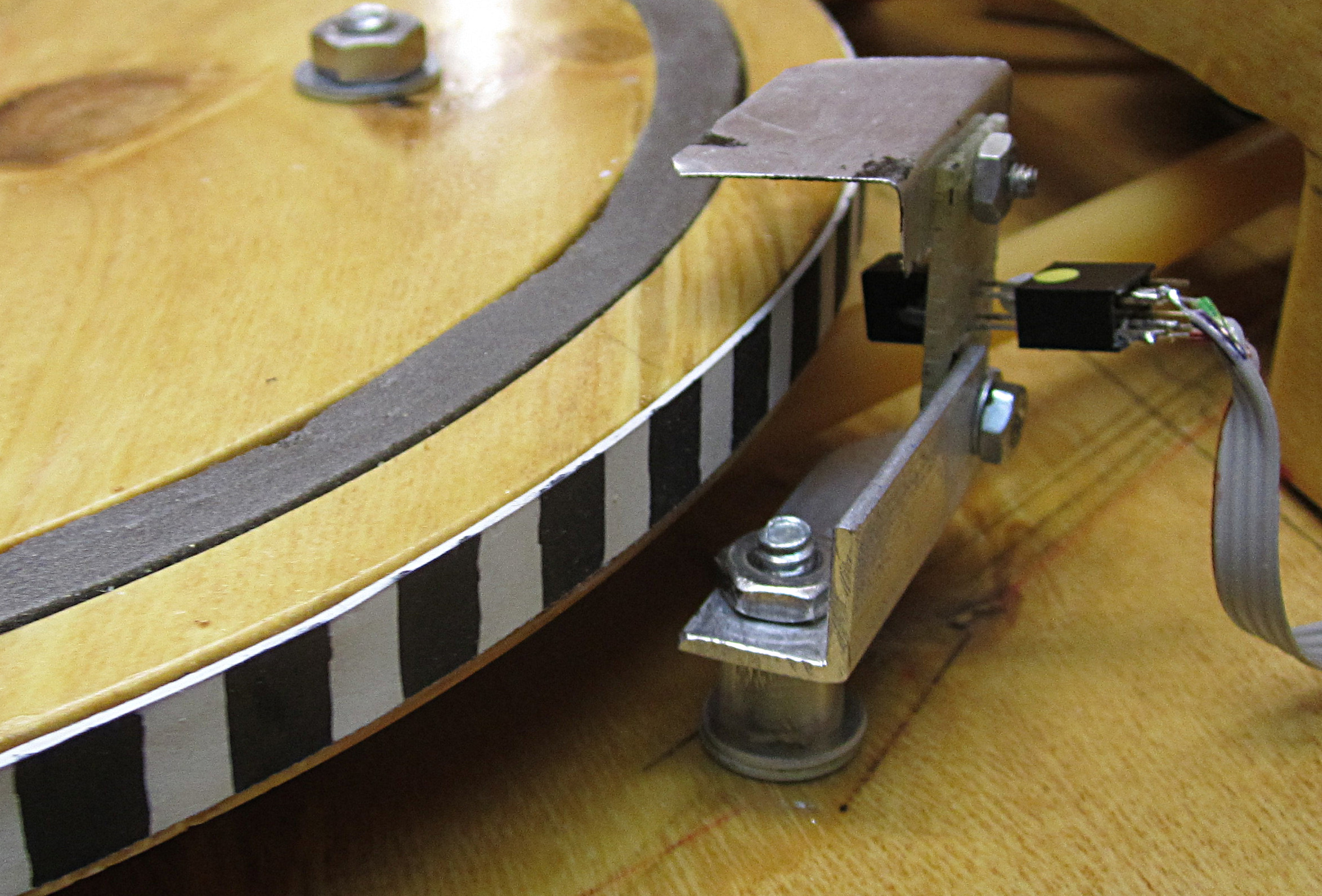
Stall detector version 1
I'm still not sure whether it was truly necessary or just feature creep. But in the initial design, I felt that there was a chance the turntable's rotation might get stalled for any number of possible reasons — critters or weather or demonic influences — and it would be bad if such condition went untended. At any rate, my controller chip had ample spare capacity, so I went ahead. All I needed was a way to tell whether the turntable was turning or not.
The first attempt (let's call this Plan Alpha) had an optical sensor aimed at a black/white striped rubber band around the turntable. As each stripe passed, the sensor would signal a high or low voltage, depending on how much light the stripe reflected. By measuring the time between voltage changes, the controller could deduce the turntable's rotation speed. Too long of a time would indicate a stall.
If that happened, the controller would shut off power to the motor. Then, every 60 seconds or so, it would restart the motor for a few seconds and check whether there was any rotation. If there was, the controller would resume normal operation, at least until the next time.
It worked really well when the machine was dry. It also worked during heavy rains, but only at night. Rain and daylight seemed to be a recipe for failure. At random times, the machine would spontaneously stop itself and go into stall-recovery mode for many minutes. One possible cause: Water made the rubber band glossy, reducing the contrast between black and white stripes. Or maybe the water made the woodwork too shiny; the light sensor was shielded from light from above, but not light reflected from below.
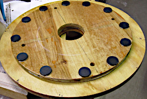
Stall detector version 2: A ring of magnets glued to the bottom of the turntable periodically trigger a reed switch.
Onward to Plan Beta. This involved gluing a dozen magnets around the underside of the turntable and positioning a magnetically sensitive reed switch where the magnets would pass overhead. As the turntable rotated, the switch would be toggled on and off as magnets moved into and out of range. Then, as with Plan Alpha, the controller would measure the time intervals and take action if too much time passed.
Of course, this approach worked fine in the workshop. Amazingly, it seems to work well outdoors too. As of November 18, it has survived an all-day rain, a snowstorm, and wide temperature swings on dry days and nights.