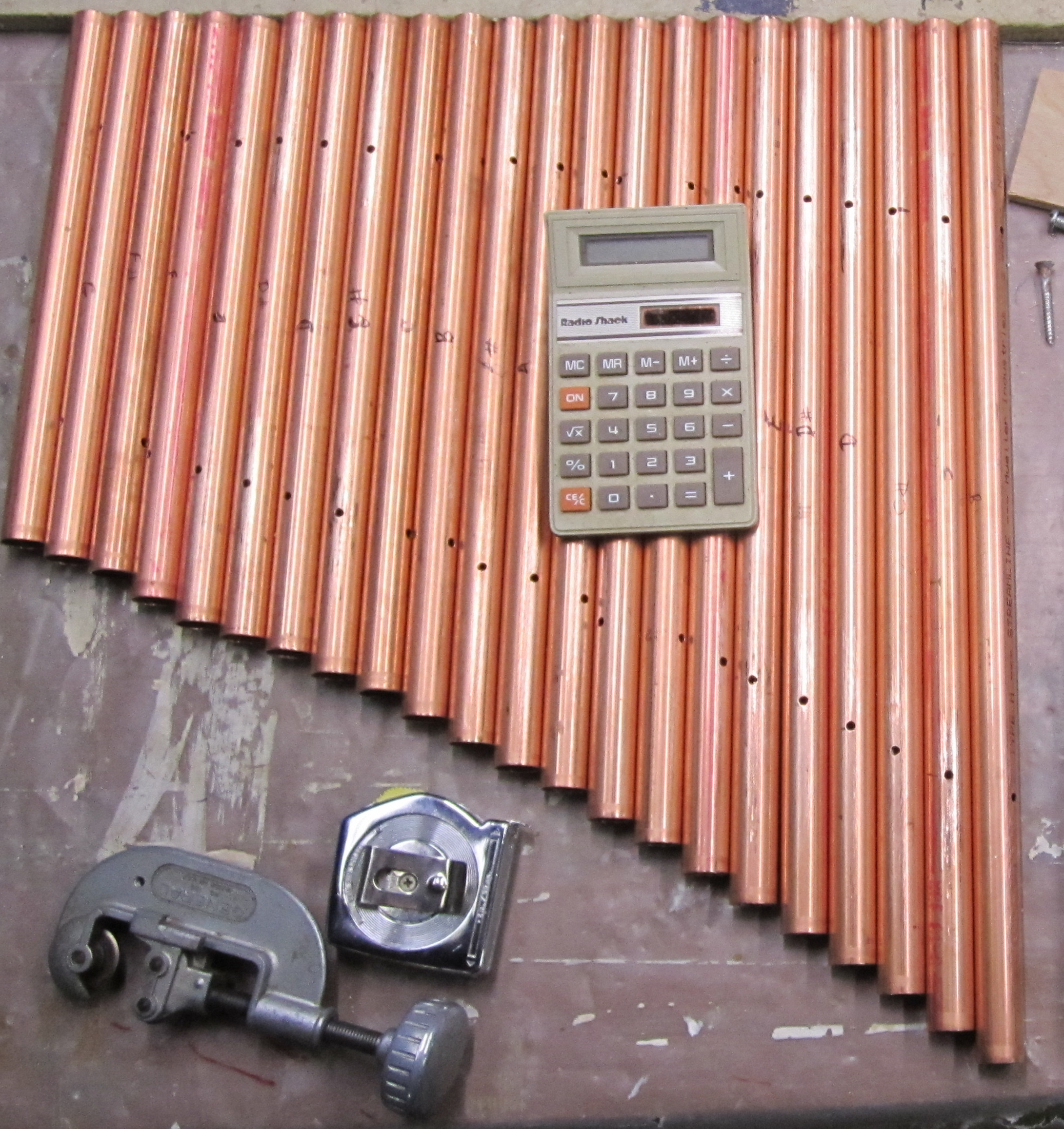
I’ve cut pipes for almost the full two octaves, from B4 to G6. (The piano's Middle C is C3.) The mounting holes are placed 22.4% of the pipe’s length from each end, which is why there’s a calculator in the photo.
Project started in early January 2020; last update is mid-March.
I have always been fascinated by the concept of a player piano, perhaps because I have no playing skill of my own. Of course, such a thing would be totally impractical to build in the basement. The mechanical linkages would demand serious carpentry chops; once built the thing would be rather large; and finding perforated paper rolls of music would be challenging. So instead of a player piano, I chose to build a player xylophone.
Well, technically a xylophone is supposed to use tuned wooden bars — xylo comes from the Greek word for wood. Ideally, one would use rosewood or a fine-furniture hardwood. But that’s expensive. I chose to use copper plumbing pipe because it is cheap, easily worked, and gives a nice bell-like tone when struck. So it’s a player glockenspiel, glock being the German word for bell. But glockenspiel is even harder to spell than xylophone, so phooey to that. It’s a xylophone.
Here’s the initial design in broad strokes:
An array of tuned copper pipes spanning two octaves or so — most tunes fit within a two-octave range;
A small solenoid for each pipe, positioned so it just taps its pipe when energized;
A low-cost microcontroller to interpret a stream of musical codes and trigger the appropriate solenoid(s). The obvious choice is an Arduino Mega board (or clone), which has 54 output pins and often can be found on sale for about $10 at the local Micro Center.
The device is a simple one, really. The only complexity (that is, the only complexity that I anticipate, going into the project) is that there’s two dozen of everything: pipes, solenoids, driver circuits and so on.
You need one pipe for each note you wish to produce. The only tricky bit is getting the pipe to be the right length so it’s in tune with the others.
I’ve cut pipes for almost the full two octaves, from B4 to G6. (The piano's Middle C is C3.) The mounting holes are placed 22.4% of the pipe’s length from each end, which is why there’s a calculator in the photo.
And what, you may ask, is the right length? There’s a formula for transverse vibration:
frequency × length ² = a constant
And what’s the constant? I found a physics journal article with a complete formula that includes the thickness of the pipe wall, the speed of sound in metal, and several mysterious fudge factors. But nuts to all that! What you do is cut one pipe to a convenient size, perhaps half a cubit, and measure its resonant frequency and its length. Plug the length and frequency into the formula to get the constant. Then the same constant will work for all your other notes.
Provided, that is, that they are all cut from the same type of pipe. My local building center carries two types, called Type L and Type M, and Wikipedia mentions two others. The difference seems to be the metal thickness. The moral is, pick one type and stick with it.
Measuring the frequency is best done with a guitar-tuning app. You can probably find a free app for your phone or computer online. I found one for my Macintosh called Talking Tuner, by Hot Paw Productions, that works pretty well. In addition to showing the frequency in Hertz, it tells you whether you are sharp or flat with respect to the nearest standard pitch.

The tuning test jig. Not shown is a notebook computer running a guitar-tuning app.
Set up a spreadsheet with the standard pitches (which you can find here), plus the constant you have worked out, to calculate a bunch of target lengths. Cut each pipe just a bit long, though. Measure its frequency and, if it’s flat, shorten it a bit with a file. (It’s really hard to lengthen a pipe if you cut it too short!) Measure, file, repeat until it’s as close as you want.
Bear in mind that temperature does affect the pitch of a metal pipe, and filing or grinding will heat the metal up a bit.
Mounting the pipes. The optimum position for a support is 22.4% of the pipe’s total length from each end. This is a null point in the pipe’s vibration pattern, so attaching a support at that spot will dampen its tone the least. I “attached” the pipes by resting them on foam-rubber weatherstrips.
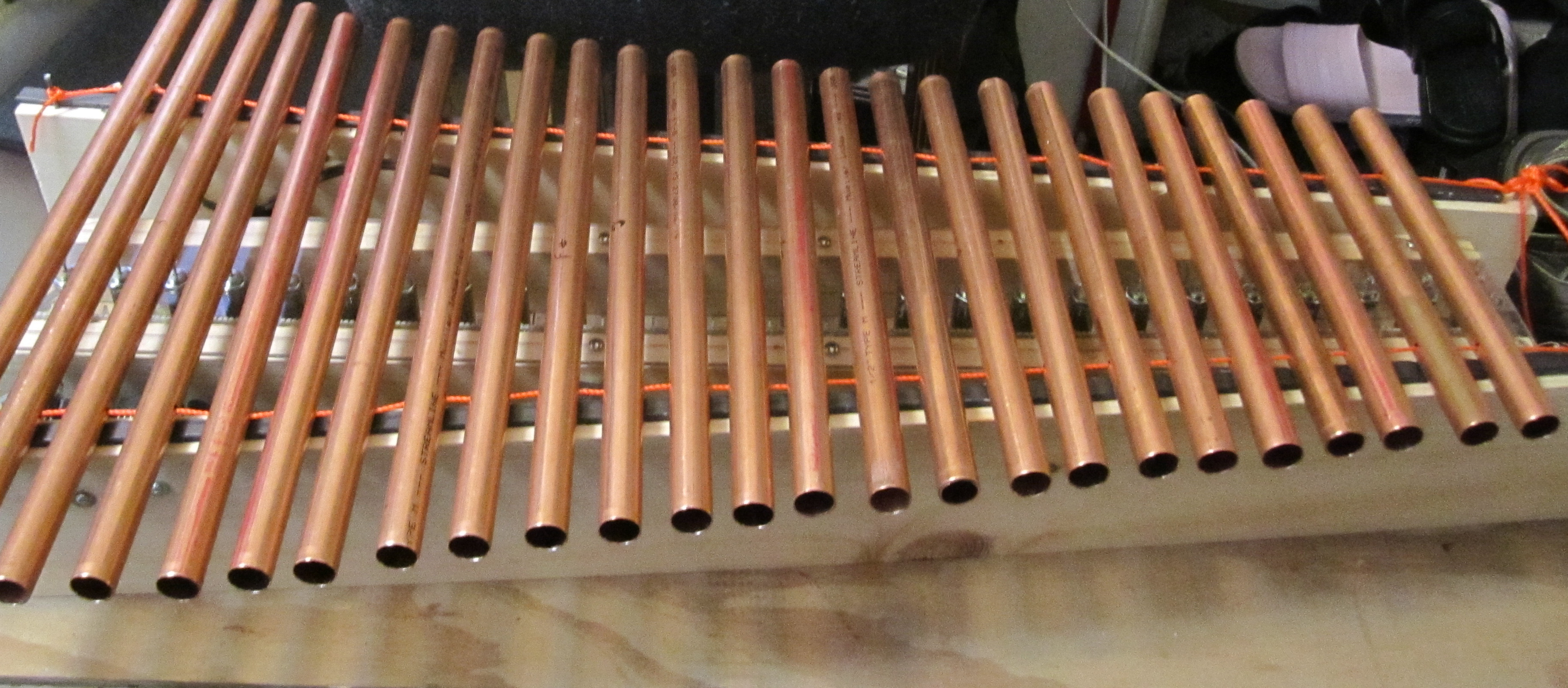
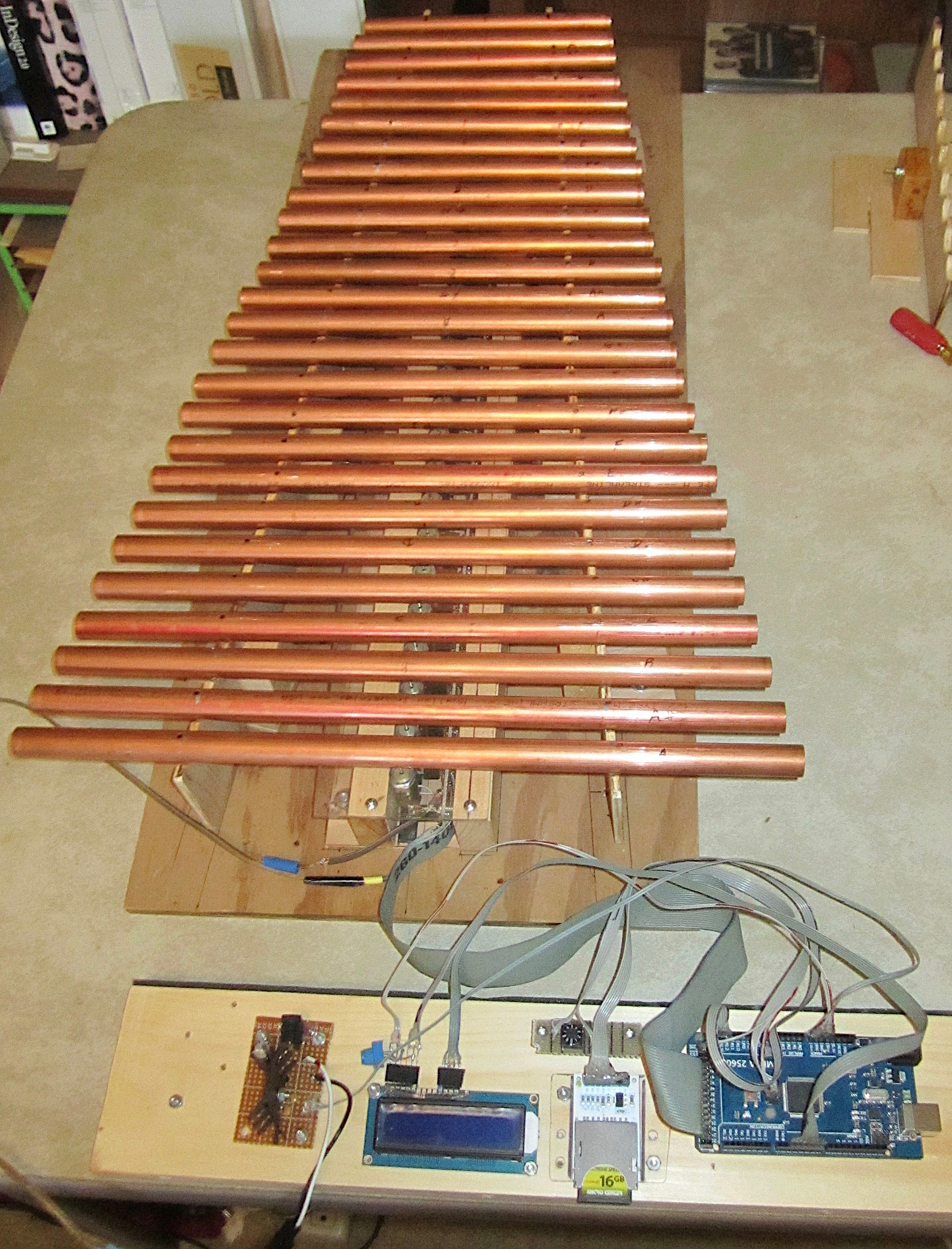
The almost-complete musical instrument. (The right-most pipe, a B-flat, hadn't been cut when I took the photo.)
To keep them from sliding out of position, I passed a string through holes drilled at the null spot in each pipe. (I suspected that drilling a hole in a pipe might affect its frequency, so I drilled before I tuned it.) Then I put blobs of hot-melt glue on the string on each side of the pipes.
I found some suitable solenoids at All Electronics. “Suitable” means they are tiny — a mere half-inch in diameter and one inch long — and not too expensive: $2.50 each if you buy 10 or more at a time. (I will confess, however, that this cost was one factor in my decision not to build a three-octave instrument.)
The All Electronics site discloses two problems with this solenoid, though. First, the plunger can fall out the back of the cylinder. Second, there’s no spring to retract the plunger when power is released. The solution to both problems is simply to mount each solenoid vertically below its pipe (let gravity work for you) and put a board underneath.
Running at their nominal 12-volt rating, the solenoids aren’t very powerful. But that’s okay; you don’t really need to strike a copper pipe very hard to get a nice tone. And if need be, you can run the solenoid at higher voltages, because the power is applied in very short pulses and so the solenoid has lots of time to cool down between notes.
In the junk box, I found both a 12-volt and an 18-volt wall-wart power supply with decent (1 amp) current ratings. Testing showed that either could work, but at 18 volts the solenoids could be energized with shorter pulses. This seemed like an advantage, so I went with it.
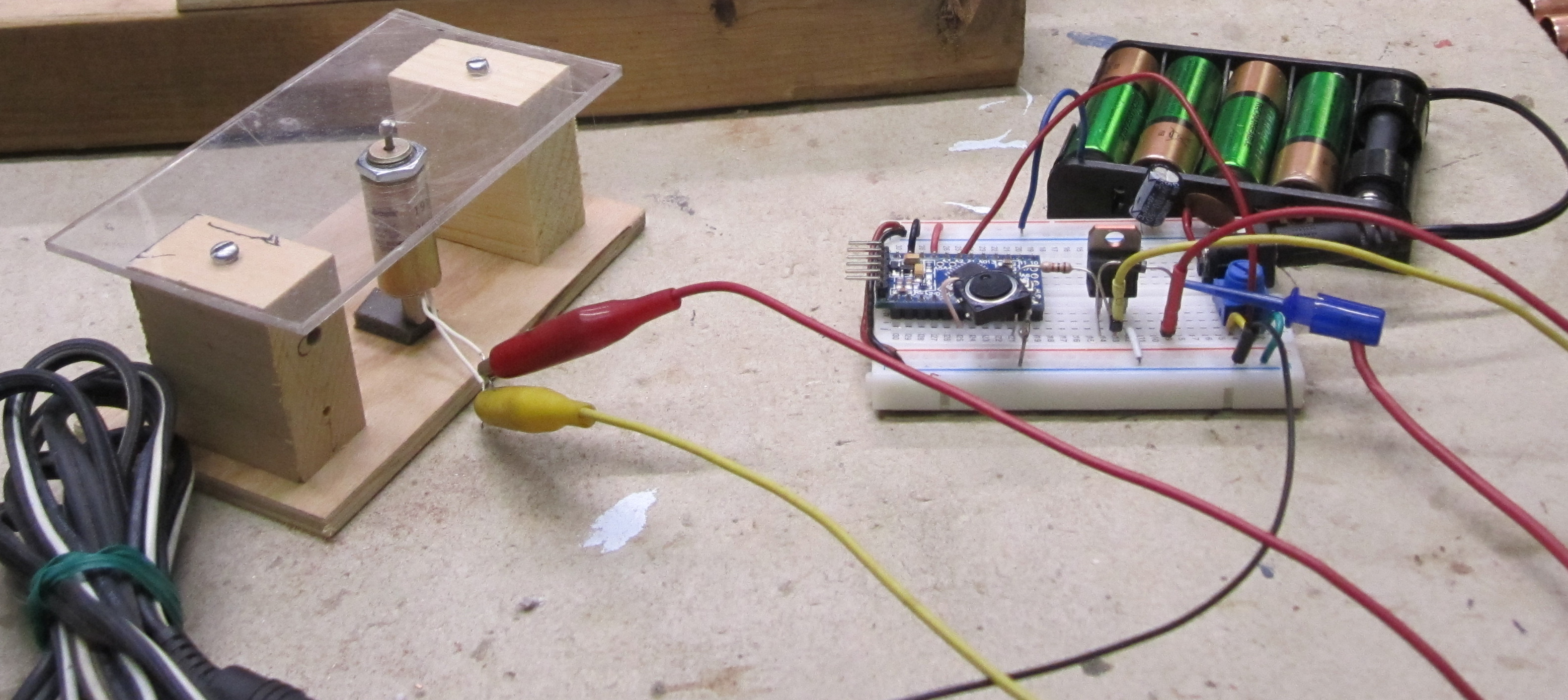
Test jig to fire a solenoid with various voltages and pulse durations.
At 18 volts, each solenoid draws about 450 milliamps. (At 12 volts, it’s 300 mA.) The Arduino controller puts out 5 volts and can safely supply at most 10 milliamps per pin. Thus, a power transistor is required for each solenoid. All Electronics was selling beefy TIP112 transistors for 50¢ each, so that’s what I used. If logic-level power mosfets had been cheaper when I was shopping, I’d have used them instead.
The solenoids are mounted in holes drilled in a sheet of polycarbonate plastic. Each solenoid is wired to its power transistor mounted on perfboard. Some basic info on the driver circuit is in this tutorial from BC Robotics.
During testing, I found that striking a pipe with the solenoid’s bare metal plunger gave an annoying clank. So I put a blob of hot-melt glue on the tip of the plunger; it cooled to a rubbery ball that improved the tone a lot.
With the solenoids and pipes in place, it was time to write some software for the Arduino Mega controller. (It would certainly be possible to use a different device: a Raspberry Pi, perhaps. But my local computer store frequently offers Arduino clones at deep discount.) The first test script simply ran up and down the scales to make sure that each note was being sounded.
The next test was to code up a few simple tunes. I picked three rounds — Row Row Row Your Boat, Dona Nobis Pacem, and White Coral Bells — because those would also verify that multipe notes can be played at once.
A recording of Dona Nobis Pacem, a three-part round. (Click to play movie.)
This test quickly revealed that the system was working. Oh, the pipes weren’t perfectly in tune, but close enough for now. And one pipe was giving a distinct “clank” when struck; probably that solenoid had lost its hot-melt blob. But there was one serious flaw: All the solenoids were adding a noticeable “thump” sound to each note.
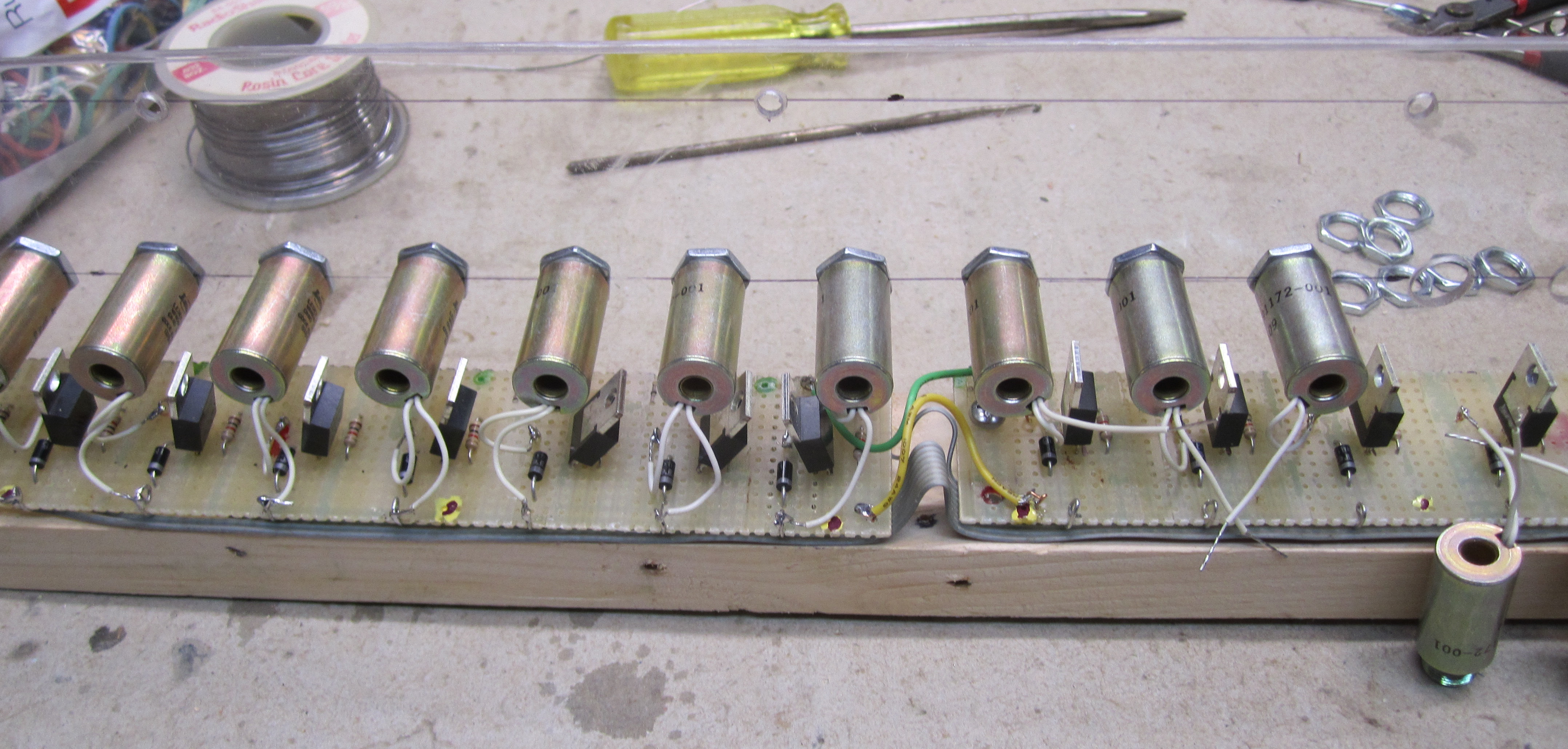
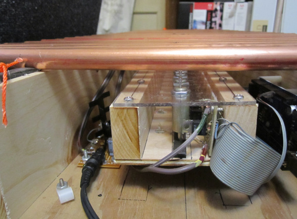
To reduce the thumps, the first step was rebuilding the solenoid assembly. I moved one of the 1x2 strips as close to the solenoids as possible. The second step was bolting it down firmly against a support board, rather than suspending it in mid-air.
Compare the photo below with the one above.
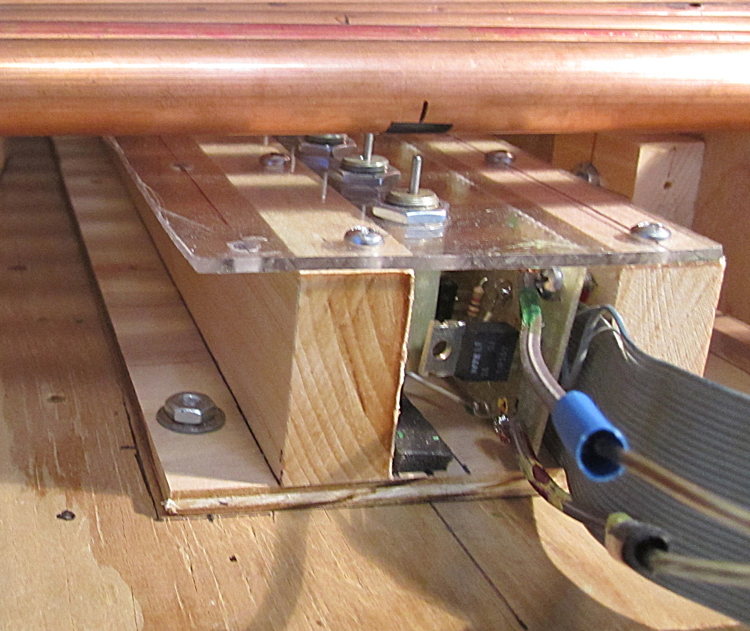
In version 2, the solenoids are mounted to minimize vibration caused by mechanical movement of the plungers. But notice that the power transistors are inside the cage. This turned out to be a Bad Thing.
Another challenge was getting all the notes to sound with equal loudness. Electronic components are subject to manufacturing variations and are only guaranteed to be "within tolerance." Alas, human hearing is rather finicky. What I left out of the initial design was a way to adjust each solenoid's force individually.
The solution wasn't hard: Put a variable resistor between each Arduino output pin and its corresponding transistor. Since I'd need to buy multiple dozens of them, I was glad to find that Electronic Goldmine had them for 25¢ - 40¢ apiece.
But adding parts to the electronics meant rebuilding the solenoid array again. Rats! There will have to be a Version 3.
Obtaining tunes. There are many online sources for free MIDI files. Among those I have returned to are:
Midi Sheet Music
8Notes.com
mfiles
Simplifying the tunes. Getting a file is only the first step. A lot of MIDI files are designed for a full-range synthesizer, so they have to be adapted to work on this xylophone. At a minimum, this means stripping out the drum and bass tracks, limiting the number of harmony tracks, and sometimes deleting individual notes. So far, the least expensive Macintosh software I've found for this is Reaper, which is free for a 60-day trial period, but then you have to buy a license for $60.
Then, it's necessary to transpose the notes to fit the xylophone's range. One method is to translate the MIDI file into human- and machine-readable CSV (comma separated values) format. Fourmilab has a free program to do such a translation. Lots of programs, including spreadsheets, databases, and Perl or Python scripts, can read CSV.
Arduino code. Then it's just a matter of writing a script to transform the CSV data into some sort of data that the xylophone can play. Here's a Perl example that outputs files in a format suitable for playing with this corresponding Arduino sketch.
The Arduino sketch supports several bits of external hardware: A small display (2 lines of 16 characters each) to show the name of the tune being played; a rotary switch to select from several playlists; and a memory card to hold lots and lots of tunes and playlists.
Here's the finished xylophone, version 2. For the photo, I placed it in the middle of a card table. That's a boo-boo: The card table amplifies any thumps from the solenoids. Just moving the assembly to the edge of the card table cut the noise significantly. Putting some sound-absorbing material, such as a scrap of carpeting, under the assembly would help even more.
Mid-March, 2020
I'm optimistic that the remaining sound-quality problems can be overcome somehow. Then what? There’s a number of possible directions to extend the device:
MIDI. Right now, tunes for the xylophone have to be hand-coded (with assistance from several computer programs) and stored in the controller’s memory. An interesting alternative would be to give the controller its own MIDI interpreter, allowing it to play the many MIDI tunes that are available from the Internet.
Dynamics. Another improvement would be some variation in intensity — in MIDI terms, velocity. Varying the length of the power pulse does affect loudness of the tone, although it's more noticeable with some pipes than others.
Add more sounds. The controller has 54 output pins, and the xylophone uses only 26. Keeping it real, I should note that another 16 pins are assigned to support useful devices, such as an SD card reader, an LCD display and a selector switch. Still, that leaves a dozen pins that might be assigned to more pipes, or to other kinds of instruments such as drums.
Robot-human duets. The xylophone pipes are being struck from the bottom, and a human player can tap the pipes from the top at the same time. The robot could be programmed as a continuo plus rythm section, upon which the human could improvise ad libitum.
The weatherstripping worked fine for a while. But within a few days, the weight of the pipes (small though it be) had permanently dented the foam rubber. The depth of the dent depended on the length of each pipe. This put some pipes closer to their solenoid, altering their tone and loudness.
On the other hand, it also meant that drilling holes and stringing the pipes had been unnecessary. Done is done, but if I had to replace any pipe (say, to correct a tuning mistake) I wouldn't bother to drill again.
Here's a different mounting system.
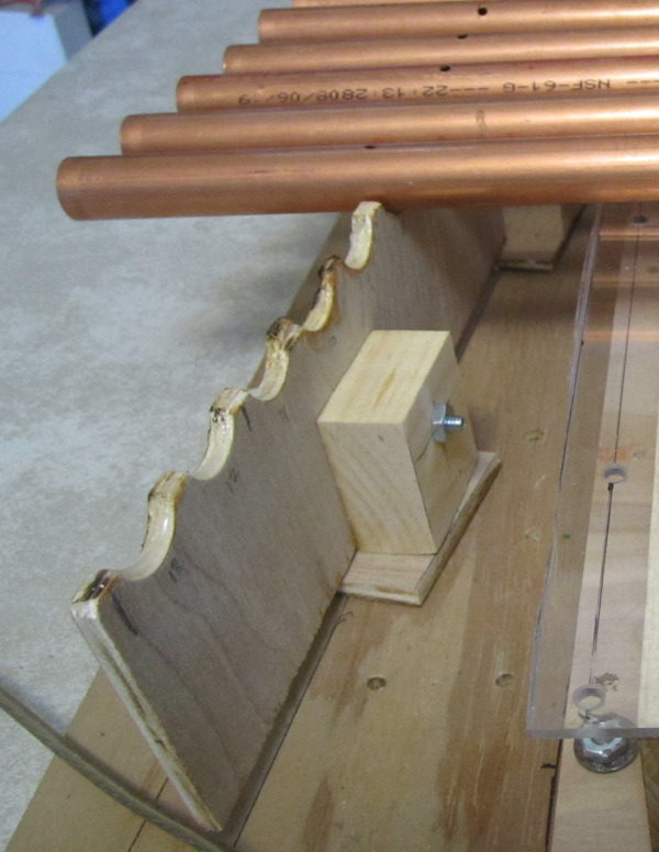
To make the scalloped supports, I cut a slab of thin plywood about 5 by 30 inches. A hole saw bored a row of holes, spaced just a hair farther apart than the spacing of the solenoids, right down the middle. Then I sawed the slab in half.
I got some of the holes a bit off-center. To compensate, I raised some of the scallops with a layer of hot-melt glue. The problem could have been avoided by using a drill press, if I had one.